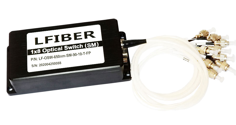
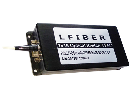
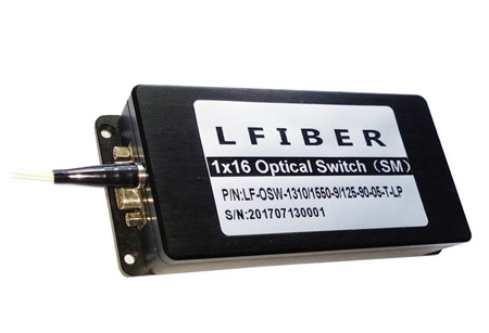
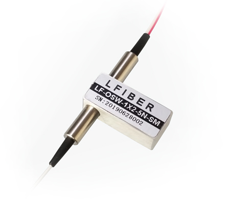
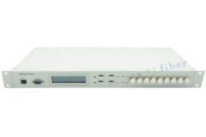
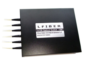
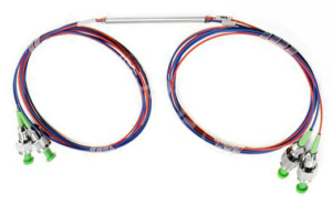
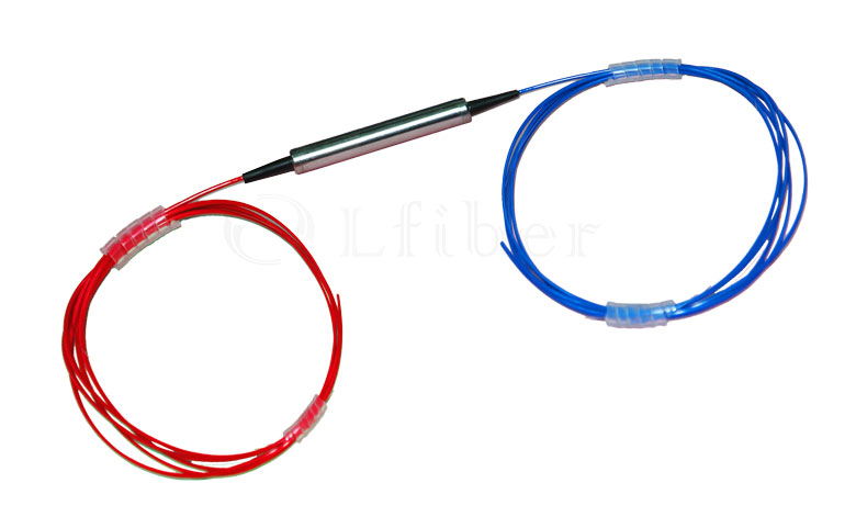
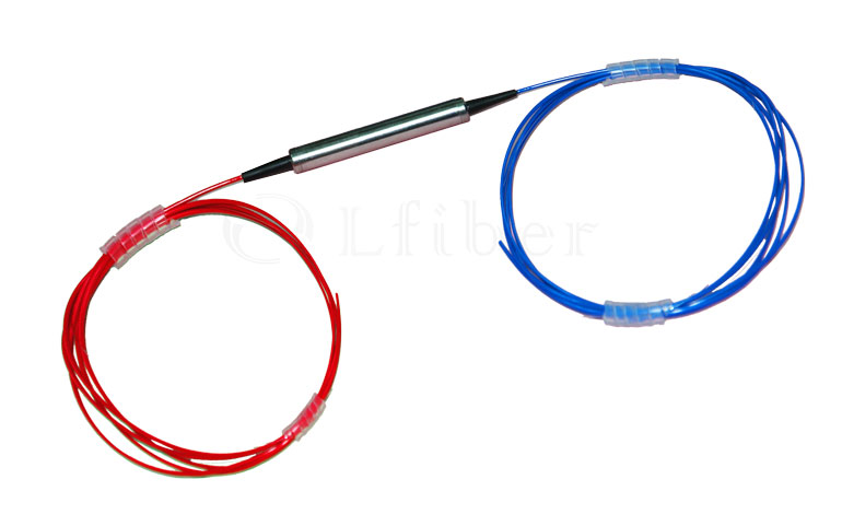
Single-Mode Fiber Optical Switches
SM Fibers, VIS-NIR Spectrum, RS232 / USB Control
FEATURES OF FIBER OPTICAL SWITCHES
- Low Insertion Loss and High Reliability
- Serial Interface (RS-232)
- Modularized Design
- Epoxy-free on Optical Path
APPLICATIONS OF SINGLE-MODE FIBER OPTICAL SWITCHES (SM FIBER SWITCHES)
- Optical Signal Switching and Routing
- Optical Network Monitoring
- Testing of Fiber Optic Component
- OTDR Testing
Specifications of the Fiber Optical Switches
Number of Channels (N) 1×N (N ≤ 16) or other channel counts on request
Fiber Type Single-mode fibers
Insertion Loss (dB) ≤ 2.0 dB @ 430-670 nm
≤ 1.5 dB @ 780-1250 nm
≤ 1.0 dB @ 1260-1590 nm
≤ 1.5 dB @ 1600-2000 nm
Operating Wavelength Range (nm) 430-2000 nm on request
Testing Wavelength (nm) 450, 532, 650, 850, 980, 1310, 1490, 1550, 1625, etc.
Return Loss (dB) ≥ 50
Crosstalk (dB) ≥ 70
Wavelength Dependent Loss (dB) ≤ 0.25
Temperature Dependent Loss (dB) ≤ 0.25
Repeatability (dB) ≤ 0.02
Lifetime (cycles) ≥ 10 million
Switching Time (ms) ≤ 8 (adjacent channel)
Power Handling (mW) ≤ 500
Power Supply 5V / 500mA
Control Mode RS-232
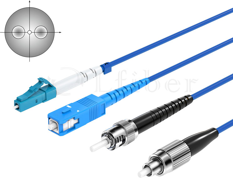
Connector FC, LC, SC, ST, SMA, etc.
Operating Temperature (℃) -20 to +70
Storage Temperature (℃) -40 to +85
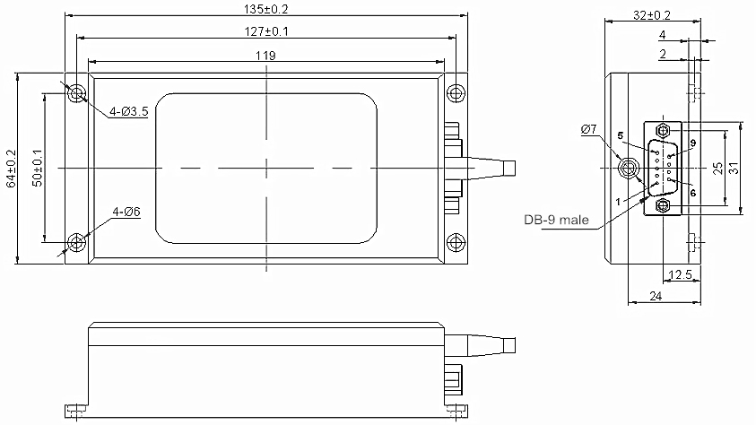
Dimension (mm) 135 × 64 × 32 mm, 19" rack or different sizes on request
- Typically, the operating wavelengths of the single-mode (SM) fiber optical switches include, but are not limited to, 444 nm, 445 nm, 447 nm, 450 nm, 454 nm, 457 nm, 460 nm, 462 nm, 465 nm, 470 nm, 473 nm, 480 nm, 488 nm, 490 nm, 509 nm, 514 nm, 515 nm, 520 nm, 522 nm, 523 nm, 526 nm, 530 nm, 532 nm, 540 nm, 543 nm, 550 nm, 561 nm, 589 nm, 600 nm, 630 nm, 632 nm, 633 nm, 635 nm, 637 nm, 640 nm, 642 nm, 647 nm, 650 nm, 655 nm, 656 nm, 660 nm, 665 nm, 666 nm, 671 nm, 685 nm, 688 nm, 780 nm, 793 nm, 795 nm, 808 nm, 830 nm, 835 nm, 845 nm, 850 nm, 852 nm, 860 nm, 905 nm, 915 nm, 930 nm, 935 nm, 938 nm, 940 nm, 946 nm, 960 nm, 975 nm, 976 nm, 980 nm, 1030 nm, 1035 nm, 1040 nm, 1055 nm, 1060 nm, 1064 nm, 1080 nm, 1300 nm, 1310 nm, 1410 nm, 1450 nm, 1475 nm, 1480 nm, 1490 nm, 1528 nm, 1550 nm, 1558 nm, 1565 nm, 1570 nm, 1590 nm, 1605 nm, 1610 nm, 1625 nm, 1645 nm, 1710 nm, 1850 nm, 1870 nm, 1900 nm, 1910 nm, 1920 nm, 1940 nm, 1950 nm, 1990 nm, 2000 nm, etc.
- For requests please see the ordering information section and specify the number of channels, operating wavelength range, control mode, etc.
- This fiber optical switch is easily controllable through LabVIEW and Python.
- Lfiber can offer a plug-and-play solution for directly programming the switch via RS232 / USB interface upon request. If there is a need, we can offer software solutions (based on Microsoft Windows OS) so that the users can easily control the optical switch (even though you don’t have any knowledge about programming) via the RS232 / USB interface on your computer.
- The fiber optical switches can be powered by a universal AC/DC adaptor that is able to convert 100-250 VAC to 5 VDC.
- Standard port/channel counts of the fiber optical switches: 1×2, 1×4, 1×8, 1×16, 1×24, 1×32, 1×48, 1×64, 1×128, etc. Other channel counts are also available on request.
- The optical switches can be installed in standard 19-inch racks. We offer customization upon request if needed. Click Rack-Mounted Fiber Optic Switch for more info.
- Lfiber’s optical switches are customizable and the specifications are subject to change without notice.
- For product customization or special requirements, please contact our sales representative.
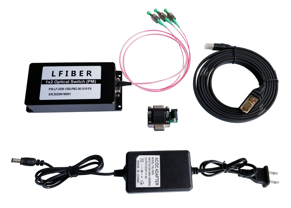
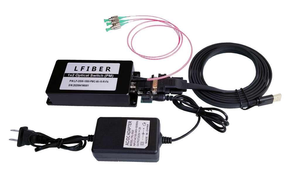
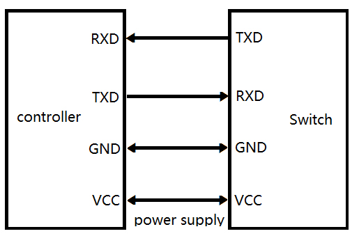
| RS232 Control via USB: Hardware Connection of the Fiber Optical Switches |
|---|
| Pin Configurations of the Fiber Optical Switches |
|---|
DB-9 Male Connector
| Pin No. | I / O | Signal | Descriptions |
| 2 | Input | RXD | Receive Data |
| 3 | Out | TXD | Send Data |
| 5 | Power | GND | Ground |
| 8 | Power | GND | Ground |
| 9 | Power | VCC1 | 5.0 ± 5% VDC Power Supply (500mA) |
| 1, 4, 6, 7 | NC | NC | Vacancy |
| Dimensions of the Fiber Optical Switches |
|---|
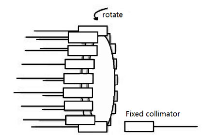
| Optical Route of the Fiber Optical Switches |
|---|
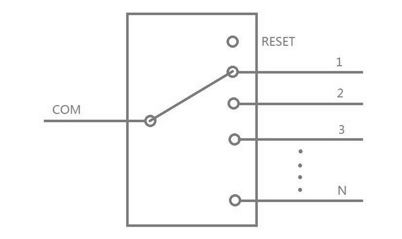
| Control Chart of the Fiber Optical Switches |
|---|
Communication Protocol
- “_” expression underline.
- Communication protocols are all capital letters.
- The communication protocol commands, “<” as the start, “>” as a terminator.
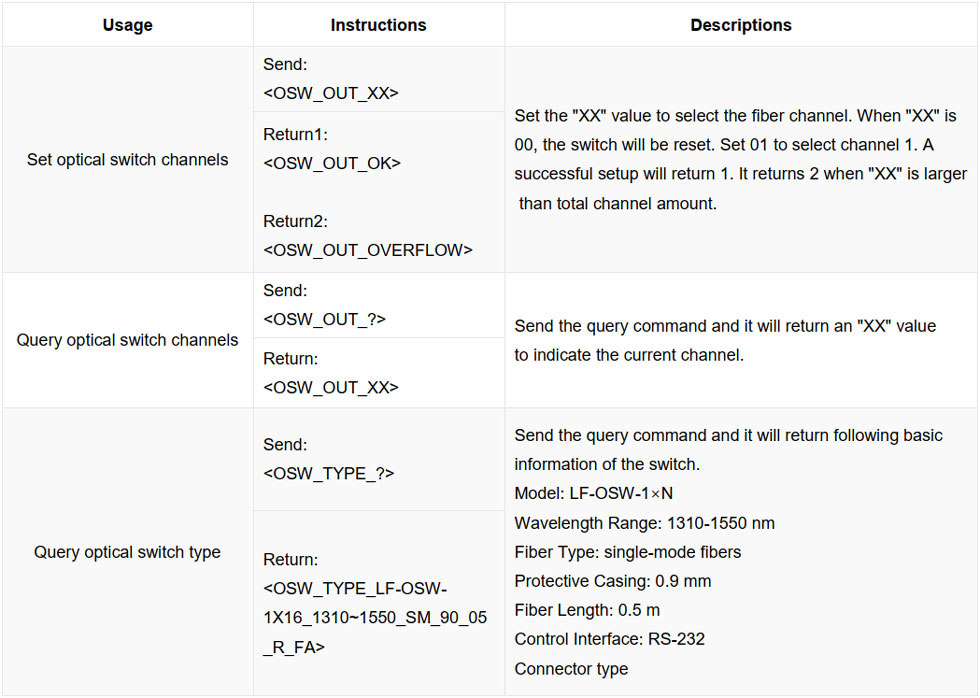
Operating Instructions
COM Settings
Baud rate: 9600 | Data bits: 8 bit | Stop bit: 1 bit | Parity bit: None | Command error return “< OSW_ERROR >”
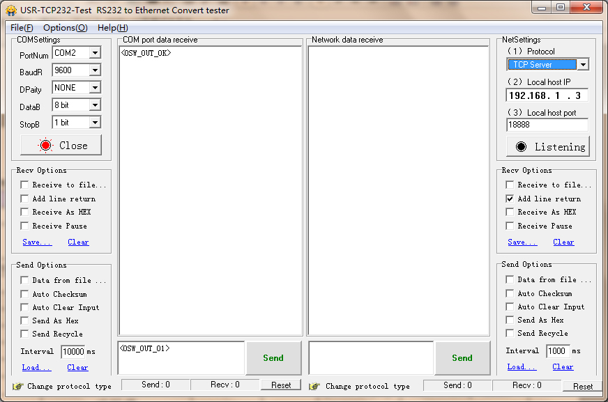
Software Control Chart (For Reference Only)
-
The fiber optical switches transmit the command to control the optical switch through RS232 serial communication. The optical switch receives the command successfully and returns the response.
-
To program the fiber optical switches directly via USB (RS232 control), we can throw in a USB 2.0 to DB9 male serial cable (RS232 converter/adaptor), and then the switch can be connected to the USB port on your device. Click USB to DB9 Male Serial Cable Driver to download the driver for the converter/adaptor.
- The optical switches are bidirectional in operation.
Ordering Information for the Fiber Optic Switches
Number of Channels Operating Wavelength Fiber Type Control Mode Fiber Pigtail Length Connector
1x2 444 nm Single-Mode Fibers RS232 (via DB9 Male) 0.50 m None
1x4 450 nm RS232 (via USB) 1.00 m LC/UPC
1x8 460 nm 1.50 m LC/APC
1x16 532 nm Custom … SC/UPC
Custom … 630 / 632 / 633 nm SC/APC
635 / 637 nm FC/UPC
650 nm FC/APC
780 nm SMA
793 nm Custom …
830 nm
835 nm
850 nm
905 nm
915 nm
935 nm
940 nm
980 nm
1064 nm
1080 nm
1300 nm
1310 nm
1450 nm
1490 nm
1550 nm
1625 nm
2000 nm
Custom …
Related Products of Single-Mode Fiber Optical Switches (SM Fiber Switch)
